How to Use Schematics to Build Electronic Circuits

In simple words, a schematic diagram for an electrical circuit can be defined as a road map to a certain destination. Schematic diagrams make use of electrical symbols and layouts to describe the connections and electrical parts necessary for building an electrical circuit. Here is a list of what you will need in order to build an electronic circuit by means of a schematic diagram.
Things Required:
– Computer with internet access
– Schematic drawing
– Circuit board
– Electrical wires
– Connectors
– Pins
– Soldering Iron
– Rosin Coil solder wire
– Any other required electronic parts
Instructions
-
1
Before you can start building an electronic circuit, you will need to obtain the schematic drawing for that circuit. You can build a circuit for an electronic device as simple as a power touch switch or as complex as a fully functional robot. Go to the ‘Discover Circuits’ official website in order to obtain free schematic drawings for almost any electronic circuit. If you can not find what you are looking for, try a Google search and browse through websites that the search engine returns against your search query.
-
2
You will need a circuit board, electrical wires, connectors and pins to complete an electronic circuit. Collect all these things at one place. You may require some additional parts as well. To determine what else may be required, refer to the circuit’s schematic diagram. Furthermore, if you plan to case the electronic circuit you are building, determine the best size of the circuit board accordingly. In order to know which pin you are supposed to install at a certain point on the board, read the alphanumeric code written on the schematic diagram against the pin in question.
-
3
After you have attached all the electrical components at their proper locations on the circuit board, it is time to solder those components in place. You will have to purchase a soldering iron if you do not already have one at your disposal. Furthermore, make sure that you have enough Rosin Coil solder wire for the project at hand. Do not leave any pin or connection unsoldered because that might create problems later on.
-
4
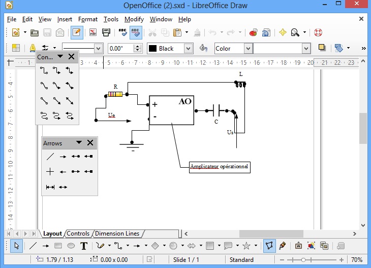
On the schematic diagram, connection that pass from above or below another connection are shown with the regular symbol; only that in this case the symbol is without a dot. A series of spikes along an electrical line in the diagram represent a resistor. Make sure that you know all the symbols properly before trying to read a schematic diagram.


