How to Fix or Replace a Single Pole Wall Switch
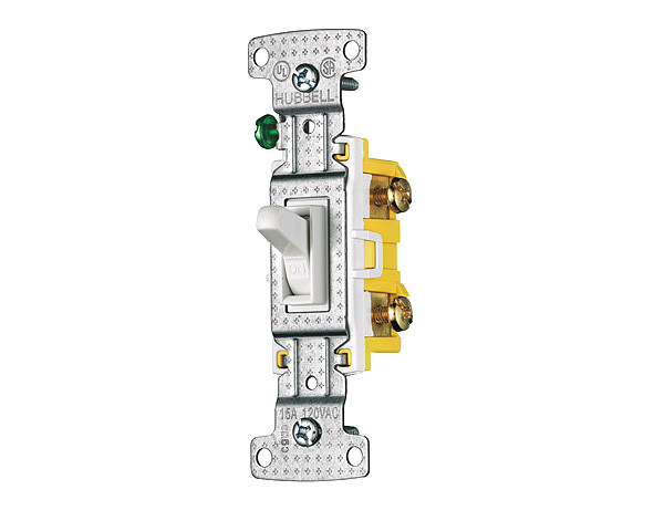
A single pole switch is the most common type of wall switch. It usually has an on-off marking on the switch lever. This type of switch has two screw terminals and some may also have a grounding screw. When installing, check to make sure that on markings shows correctly when the switch lever is up.
In a single pole switch, a hot circuit wire is attached to each screw terminal. However, the color and number of wires inside the switch box will vary depending upon the location of the switch on the electrical circuit. If two cables enter the box, the switch is located in the middle of the circuit.
Each cable has a white and black insulated wire, plus the bare copper grounding wire. The black wires are hot and are connected to the screw terminals on the switch. The white wires are neutral and earth join together with wire connector. Grounding wires are pigtailed to the grounded box.
If one cable enters the box, the switch is at the end of the circuit. The cable has a white and a black insulated wire plus beer copper grounding wire. In this installation, both of the insulated wires are hot the white wire may be labelled with black tape or paint to identify it as a hot wire. The grounding wire is connected to the grounded metal box.
Recommended tools:
neon circuit tester
continuity tester
combination tool
Materials needed:
fine sandpaper
anti-oxidant paste (for aluminum wiring)


Instructions
-
1
Turn off the power to the switch at the main service panel, then remove the switch cover plate.
-
2
Remove the mounting screws holding the switch plate to the electrical box.
-
3
Holding the mounting straps, carefully pulled the switch out from the box.
-
4
Test for power by touching one probe of the neon circuit tester to the grounded metal box or to the bare copper grounding wire, and touching the other probe to each screw terminal. The tester should not glow.
-
5
If the neon circuit tester close, there are still power entering the box. Return to the service panel and turn off the correct circuit.
-
6
Disconnect the circuit wires and remove the switch.
-
7
Test switch for connectivity and buy a replacement if the switch is faulty.
-
8
If the circuit wires are too short, lengthen them by adding detail wires.
-
9
If the wires are broken or nicked clip off the damage portion using the combination tool. Strip the wires of various about ¾” of bare wire at the end of each wire.
-
10
Clean the bare copper wire with fine sandpaper if they appear darkened or dirty.
-
11
If the wires are aluminum, apply anti-oxidant paste before connecting the wires.
-
12
Connect the wires to the screw terminals on the switch. Tighten the screws firmly, but do not over tighten. Over tightening may strip the screw threads.
-
13
Remount the switch, carefully tucking the wires inside the box. We attached the switch cover plate and turn the power on to the switch at the main service panel.
Next%20stop%3A%20Pinterest "Pin It")


